Creating a 2D Top-Down Game with a "Y-Axis"
This article is also published on Zhihu: Creating a 2D Top-Down Game with a “Y-Axis” - Zhihu (zhihu.com)
Thanks to everyone who liked and favorited!
Imagine a small bridge with an archway. The player first goes up the bridge from the left, then down from the right, and finally walks through the archway in the middle.
This is a very simple and common scenario. However, implementing it in a 2D top-down game is more complex than it might seem – how can the collision box that prevents the player from jumping off the bridge not also block the player trying to pass through the archway?
You’ve Actually Been Walking in a Maze All Along
Typical 2D top-down games usually omit the design of “ground height”. Most of the terrain players see is purely visual; it’s actually just a flat plane composed of textures and collision boxes. When players move between these “ground layers”, it’s more like navigating a 2D maze.
This approach is clearly a cost-effective compromise – in most cases, players don’t care about the specific implementation details of the game; as long as the terrain “looks like it has height”, it’s sufficient for most game needs.
But what’s the cost, Gul’dan? Please look at the following scenario:

This is a common scene in games, and it doesn’t seem much different from Figure 1, except that the character has moved behind higher terrain. Now, please pay attention to point A in the image. If the player wants to move to this position, how should they do it?
The answer is: You don’t know!
Dead Zone Defect
Why? Because it creates ambiguity in Y-coordinate mapping. Point A in the image appears to be a precise coordinate, but it’s not: a ray from the camera through point A actually penetrates two planes in this scene. This means that point A in the scene actually represents two different locations with the same X and Z coordinates but different Y coordinates, making it difficult to determine the destination.
The following diagram can help you better understand the current situation:
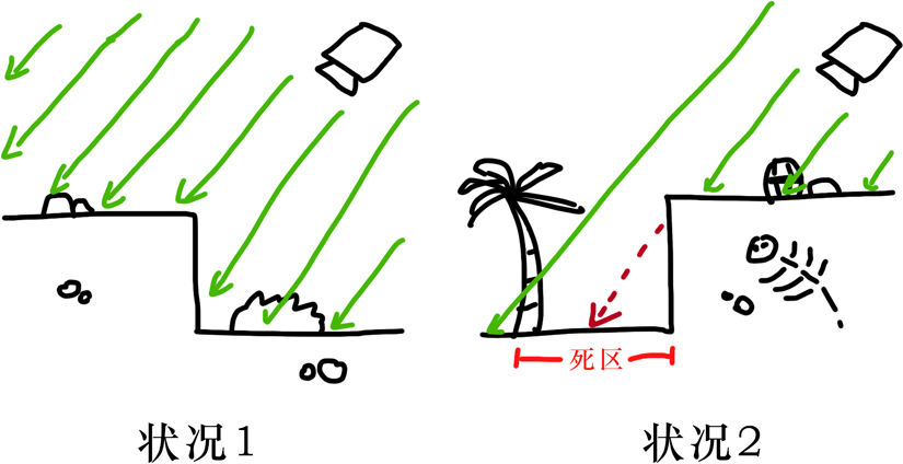
In Situation 1, each plane is penetrated by a ray from the camera only once. At this point, every (x, z) coordinate in the scene corresponds to a unique y coordinate, so there are no issues. Figure 1 in this article represents this situation.
In Situation 2, some terrain obstructs other terrain (from the camera’s perspective). This causes some rays to pass through both the obstructed area and the obstructing area simultaneously. If a coordinate point is chosen within these areas (dead zones), it will result in one coordinate corresponding to multiple actual locations.
Compromise
For most top-down 2D games, the solution to this problem is simpler and cruder than you might expect – either directly prohibit players from entering these areas, or make one of the conflicting areas unreachable, configuring collision boxes only for the other area.
For example, in this sample game, the player character can only move downwards to the position shown in the figure below – clearly, the developer configured the collision area according to the top surface of the rock wall. It’s also clear that a part of the area that should have been reachable (behind the rock obstruction) has become unreachable due to this compromise.

Another common solution is to directly use 3D models and then achieve a visual 2D effect through 3D-to-2D rendering. However, this situation actually falls under the category of 3D games and is outside the scope of this article, so it will not be discussed in detail here.
This characteristic of 2D top-down games somewhat reduces the interactivity of the map. In fact, some early games of this type often designed in-game entities to be cartoonish and small, focusing more on gameplay elements like combat, special effects, or mechanics to leverage their strengths and mitigate weaknesses. Over time, players even stopped expecting terrain interaction when facing such games – they would think: “Oh, there’s a castle here, let’s go around it” rather than “Let’s sneak through the dog hole, say hi to the guy on the balcony, and then come out from the second floor.”
Of course, this can be a stylistic game feature. But interactivity in games is like Mount Everest to a climber; it’s a standard of pursuit that never ends. Furthermore, for many small studios, the cost of creating and rendering 3D models is often high. Is there any way to alleviate this dead zone defect in 2D top-down games?
Note: This article only discusses technical feasibility. Dimensions such as necessity in game design or commercial popularity will not be extensively explored. You are also welcome to share your thoughts ;)
Correctly Mapping Height
Top-down games are not entirely incapable of handling vertex information and collision boxes on the Y-axis. Simply put, if developers can manually set collision boxes for each height layer and switch them dynamically, they can achieve 3D-like collision effects.
Handling (X, Z) Plane Collisions
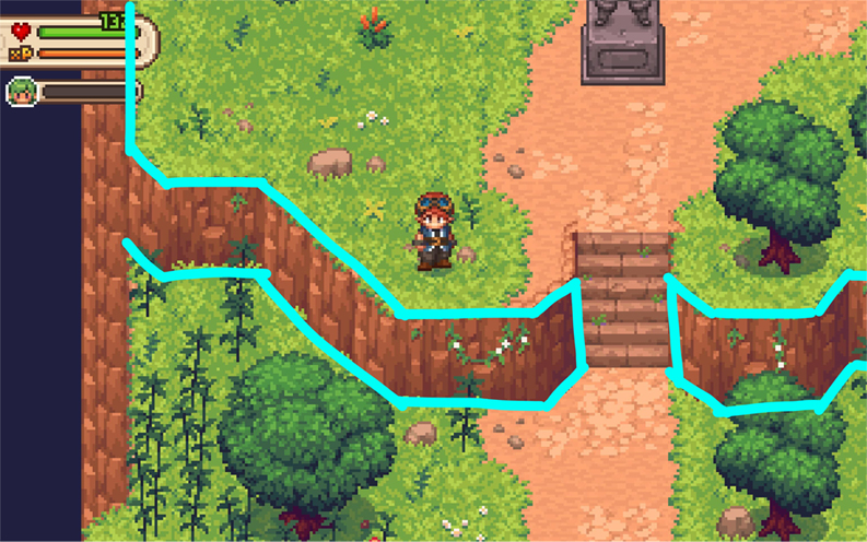
More precisely, entities on the map should respond to different collision areas at different “height layers”. Using Figure 2 again, when the player stands on a lower platform, they should only interact with the lower collision box (blue outline in the figure below), and when standing on a higher platform, they should switch to using the higher platform’s collision box (purple outline in the figure).
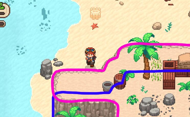
In this way, the layered collision boxes implicitly carry the Y-coordinate information of their surrounding areas, giving the entire scene a pseudo-3D feel. The drawing style shown here uses the height of the terrain as the granularity for division. Considering that drawing collision boxes for every tile would be quite complex, we’ll only do simple modeling for now.
Now, let’s try to construct such a map using Tilemap in the Unity engine:
The red squares represent collision blocks. The figure shows collision boxes for two different height layers.
Drawing collision boxes for each required height in the scene is not complicated; in fact, as long as you handle layering properly, it’s as easy as drawing a single layer of collision boxes. Unity provides LayerMask and SortingLayer properties for each GameObject, used to control its logic layer and rendering order layer, respectively.
As shown in the figure below, Unity allows developers to customize the physical interaction relationships between logic layers. We can set a height Layer for objects containing collision boxes and then configure collision relationships in Unity’s Layer Collision Matrix: only allowing collisions between layers of the same height.
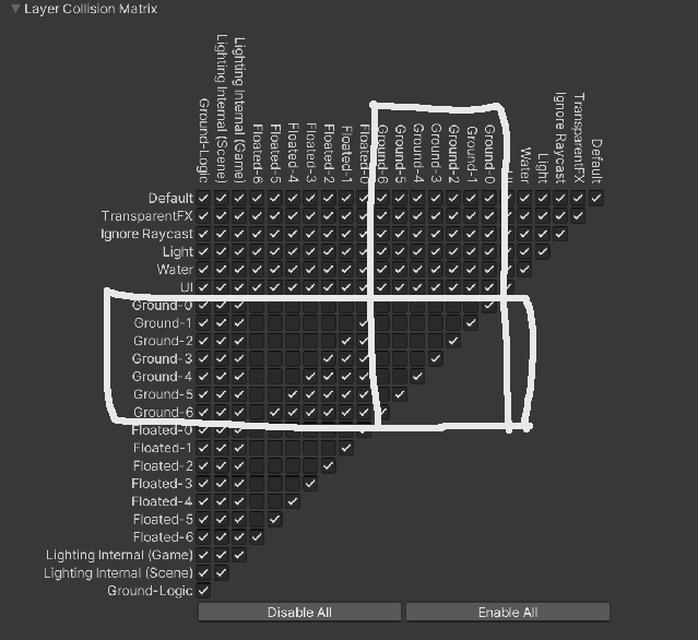
Note: Layer Masks in Unity are stored using 32-bit masks, so pay close attention to their settings and modifications.
Handling Rendering Order
After initially creating a multi-layered collision model, we also need to render different height models in the correct order. For the X-Z plane (the plane the player stands on) in a top-down perspective, planes that are “higher” are always closer to the camera and should be rendered first. In the scene shown below, plane C always obscures plane B, which is lower, and by the same principle, they also obscure ground plane A.
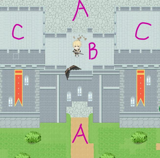
Now let’s consider the rendering of X-Y planes (i.e., walls facing the camera). Their logical height is actually between the lower and higher points connected by the “wall”. Similarly, entities within a height layer – such as the player character in the figure, located between height B and C, or the bushes on the ground, located between A and B – are always obscured by higher ground layers and always obscure the ground they are “standing” on. Objects within the same height layer follow “Z-coordinate priority sorting” – a rendering method commonly used in traditional top-down games.
Based on these designs, we’ve built a prototype for Sorting Order as shown in the figure:
In the figure above, ‘grd’ represents the X-Z plane, and ‘upr’ represents the X-Y plane. The subsequent numerical subdivisions are used to arrange objects with different orders within the same layer (e.g., ground and grass growing on it). Readers can temporarily focus only on the prefixes in the naming.
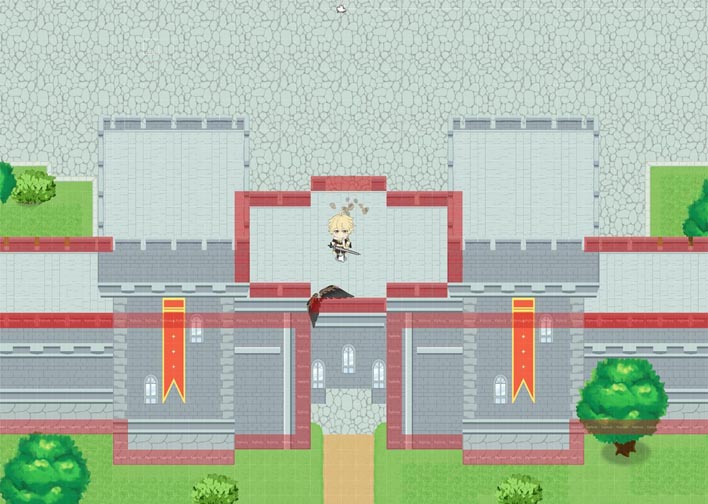
At this point, we can achieve the effect shown in the figure below:
You can see that when passing through the city gate, the player character is successfully obscured by the archway of the gate, because the tiles forming the archway have a greater logical height and rendering priority than the player. Unlike typical top-down games, our approach objectively maps the map’s height rather than superficially distinguishing between “so-called foreground” and “so-called background”.
“Stairs”
As of now, we have been using Unity’s built-in Layer Mask and Sorting Layer properties. Setting them individually can easily add unnecessary trouble during maintenance, so consider creating a dedicated Height2D component to encapsulate the “height” property. Readers can design modules according to their project needs; the Properties below are for pseudocode reference only.
In games, an entity’s height often changes: players might expect to ascend to higher terrain via stairs, and monsters might wander to areas far from their spawn points. The player’s initial height can be set via static adjustment of the Height2D.height property, but how can we dynamically identify the player’s current height?
Consider the model shown in the figure below:
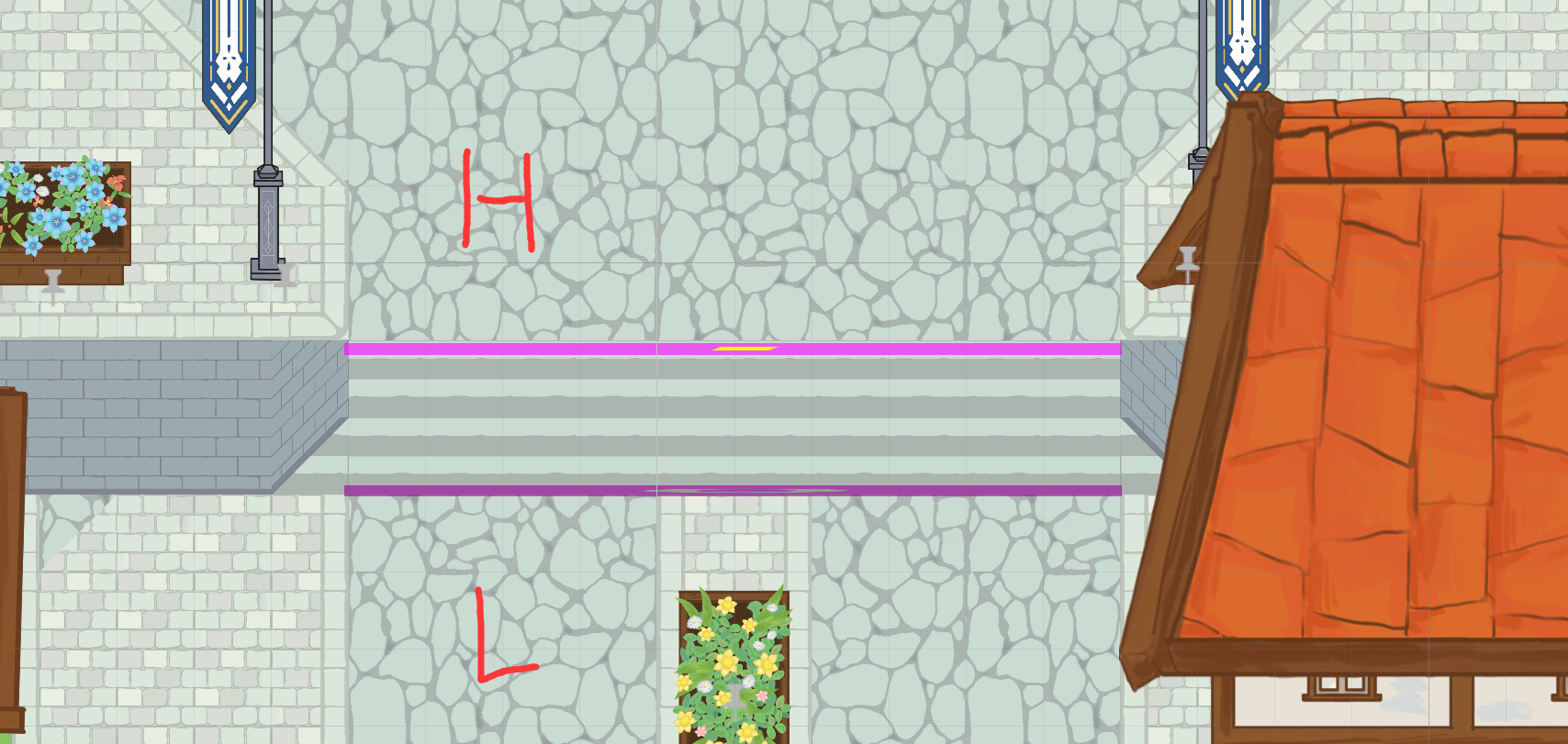
In the figure, L denotes lower (low ground) and H denotes higher (high ground). Notice the two purple lines labeled 1 and 0 between them; these lines are the key to height switching. In reality, they are a set of “logical stairs”, as shown in the figure below:
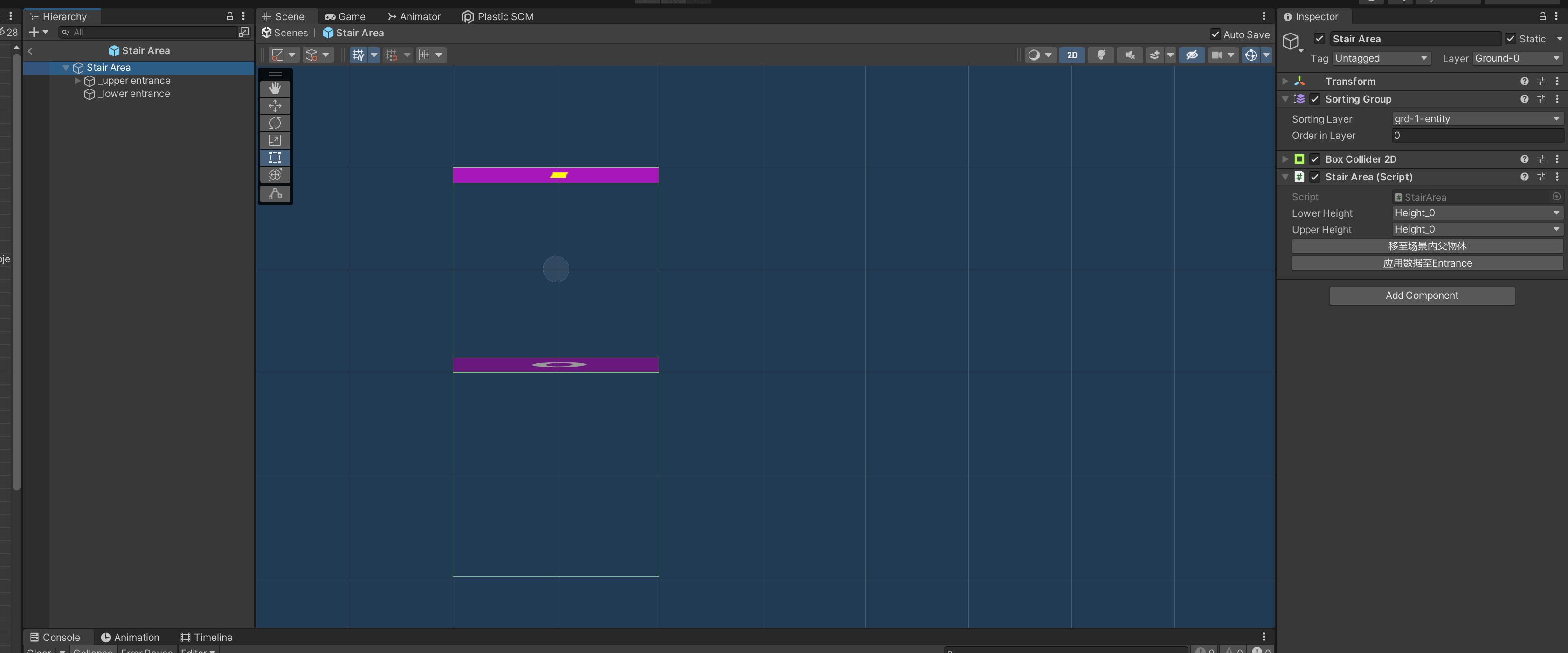
The logical stairs have two entrances, each equipped with a component that switches the entity’s functionality. When an entity enters the stair’s detection area, the stair script changes the Height2D.height property of the entity passing through it, achieving the effect of switching height. You can place these “logical stairs” in actual stair areas in the scene, or any area with similar height-switching functionality, to enable player movement up and down.
The figure below shows the application of “logical stairs” in a demonstration scene:
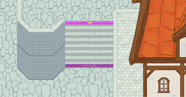
It can be seen that “logical stairs” are not only applicable to traditional stairs but also to other height-switching devices common in game scenes, such as ladders.
After completing the height switching logic, we can easily achieve the effect shown below:
Please note that in the process shown in the figure above, the Player’s height property changes dynamically (0 => 1 => 2 => 1).
Here is an example with a more pronounced effect:
In this scene, the player glides from above the city wall (height 2) and lands on the ground (height 1). You can see that the collision boxes that previously surrounded the player on the wall immediately become invalid, allowing the player to pass through those areas and emerge from the city gate. This also answers the “bridge archway model” problem mentioned at the beginning of this article.
A More Scientific Approach
For small to medium-sized projects, the layered collision boxes and height field mentioned above are a feasible solution. However, fundamentally, each coordinate in a 2D top-down map only carries X and Z plane coordinate information and lacks Y coordinate information, which is the root cause of our difficulty in mapping height.
From a more purely algorithmic and mathematical perspective, we can also consider the following design:
1 | enum SpaceType : int |
In the code above, we represent map coordinates with a new data structure. In addition to the traditional X-Z coordinates, we’ve added a YSpace dictionary to represent the Y-space at the current planar coordinates. The dictionary’s Key represents each non-empty Y coordinate, and the Value indicates the type of block present at that coordinate (solid/slope).
This approach can more easily represent complex terrain, even terrain with hollow structures:
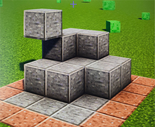
The structure shown in the figure above can be defined using the following pseudocode: (Assume the left gray vertex is the origin, and right-up is the positive direction)
1 | // 四个高度为0的地块 |
This data structure clearly establishes more rigorous rules on a mathematical level – it truly assigns a Y coordinate to each planar point.
Theoretically, it is feasible to write TerrainParser for this model and achieve an effect similar to what was described above. However, considering the space and performance overhead of assigning a dictionary to store Y space for each sampling point, as well as the complexity of implementing pathfinding algorithms under this model, this approach may not effectively replace the first implementation mentioned in this article in engineering practice.
End
To access the example game in this article,
Welcome to follow the author’s GitHub: SHthemW (S.H.W) (github.com)